Hioki 3196 Power Quality Analyzer
No stress rentals! We help you to choose the equipment that you need, we expedite shipment, and follow up.
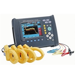
Features & specifications
- Detects high-frequency transients
- Measures harmonics to the 50th
- Measures power factor, sags, swells, flicker, and transients
- Simultaneous measurement of 4 voltage channels and 4 current channels
- Voltage ranges to 600 Vrms, current to 5000 Arms depending on CT
- Memory capacity can be configured, minimum 32 MB with rental units
- Can be battery powered with rechargeable battery pack
- RS-232 as well as LAN interfaces
- Available for Rent and for sale (Used)
| Applicable standards | IEC61000-4-30:2002, IEEE1159, EN50160:1999 |
|---|---|
| Clock functions | Auto calendar, auto leap year, 24-hour clock |
| Real-time clock accuracy | Within ±0.3 s/day (when the 3196 is turned on) |
| Internal memory capacity for data | 13 MB (time series and event data) |
| Maximum recording interval | 1 month (internal memory) |
| Measurement time control | Manual/Specified time |
| Recording item setting patterns | Power, P & Harmonics, and All Data |
| MAX/MIN/AVE values | AVE values, ALL values (maximum, minimum, and average values) |
| Interval selections | 1, 3, 15, or 30 seconds, 1, 5, 10, 15, or 30 minutes, 1 or 2 hours |
| Event settings | All measurement settings except flicker and inter-harmonics |
| Event threshold value setting | OFF or desired numerical value |
| Maximum number of recording events | 100 (internal memory), (Simultaneous events count as 1 event.) |
| Power supply | 12 V DC from the AC Adapter 9458 or Battery Pack 9459 |
| Maximum rated power | 40 VA |
| Continuous operating time with battery | Approximately 30 minutes (9459 battery pack) |
| External dimensions | Approximately (298W x 215H x 67D)mm (11.73 x 8.46 x 2.64)in (not including projections) |
| Mass | Approximately 2.25 kg (79.4 oz.) (including 9459 battery pack |
| Standard accessories (Shipped with Hioki 3196) |
Quick Start Guide Documentation CD Manual for PQA-HiView Pro PQA-HiView Pro CD 7.2V Battery Pack Power Card Hard Carrying Case 1m (3 ft.) LAN Crossover Cable 500A Clamp Sensor, qty. 4 Leads, qty. 4 (Yellow, Red, Blue, and Black) Leads, qty. 4 (Black) Compact Flash Adapter (2E4997) 32 MB (or greater) Compact Flash Memory Card 12 Vac Adapter 400Hz Measurement Function Manual EN50160 Mode Instruction Manual Multi Card Reader with USB Cable |
| Measurement line types | Single-phase 2-wire, Single-phase 3-wire, Three-phase 3-wire (3P3W2M, 3P3W3M) or Three-phase 4-wire, plus one extra input channel |
|---|---|
| Input channels | Voltage: 4 channels (U1 to U4) (channel U4 can be switched between AC and DC) Current : 4 channels (I1 to I4) |
| Input methods | Voltage between U1, U2, and U3 without inter-channel isolation Voltage between U1 to U3 and U4 with inter-channel isolation Current input by clamp-on sensor |
| Input resistance | Voltage: 4 MΩ ±10% (differential input) Current: 200 kΩ ±10% |
| Measurement method | Simultaneous digital sampling of voltage and current PLL synchronization (automatically switches to fixed clock during dropouts, so sampling is never interrupted) |
| PLL synchronization channel source | Voltage at either U1, U2, or U3 |
| PLL synchronization frequency range | 42.5 to 69 Hz |
| Sampling frequency | For calculations (including DC measurement): 256 points/cycle, 256 points/8 cycles (for 400 Hz) For harmonic and inter-harmonic analysis: 2048 points/10 cycles (for 50 Hz), 2048 points/12 cycles (for 60 Hz), 2048 points/80cycles (for 400 Hz) For transient overvoltage (impulse): 2 MHz |
| A/D converter resolution | For calculations (including DC measurement): 16 bits For transient overvoltage (impulse): 12 bits |
| Voltage measurement range | Channels 1 to 3: 150.00, 300.00, 600.00 Vrms Channel 4: 60.000, 150.00, 300.00, 600.00 Vrms ±60.000, 600.00 V pk (DC measurement) |
| Voltage crest factor | 3 or less |
| Current measurement range | With Model 9694 sensor: 5.0000, 50.000 Arms With Model 9660 sensor: 50.000, 100.00 Arms With Model 9661 sensor: 50.000, 500.00 Arms With Model 9667 sensor: 50.000, 500.00 A or 500.00 A, 5.0000 kArms With Model 9669 sensor: 100.00 A, 1.0000 kArms |
| Current crest factor | 4 or less |
| RMS voltage | Measurement method: True RMS (calculated continuously every 10 or 12 cycles at 50 or 60 Hz respectively) Range selection: Manual (channels 1 to 3 are set in the same operation) Measurement accuracy: AC ±0.2% rdg. ±0.1% f.s. DC ±0.3% rdg. ±0.4% f.s. |
|---|---|
| RMS current | Measurement method: True RMS (calculated continuously every 10 or 12 cycles at 50 or 60 Hz respectively) Range selection: Manual (channels 1 to 3 are set in the same operation) Measurement accuracy: ±0.2% rdg. ±0.1% f.s. + clamp-on sensor accuracy |
| Transient overvoltage (impulse) | Measurement method: 2 MHz sampling Measurement range: 2000 Vpk Display items: 4 ms waveform (2 ms before and after center peak) Period: Period exceeding threshold (max. 4 ms) Minimum detectable duration: 0.5 μs Measurement accuracy: ±5.0% rdg. ±20 V (1000 V DC and 700 Vrms/100 kHz) |
| Voltage swell (rise in RMS voltage) | Measurement method: True RMS (a single cycle is calculated by overlapping each half cycle) (The voltage between lines is measured for three phase 3-wire lines, and phase voltage is measured for three phase 4-wire lines.) Display items: Amplitude and duration of swell Measurement accuracy: Same as RMS voltage |
| Voltage dip (drop in RMS voltage) | Measurement method: True RMS (a single cycle is calculated by overlapping each half cycle) (The voltage between lines is measured for three phase 3-wire lines, and phase voltage is measured for three phase 4-wire lines.) Display items: Amplitude and duration of dip Measurement accuracy: Same as RMS voltage |
| Instantaneous Interruption | Measurement method: Same as voltage dip |
| Frequency | Measurement range: 42.500 to 69.000 Hz Measurement source: Voltage (same as the PLL synchronization source) Measurement accuracy: ±10 mHz (10 to 110% of range, with sine wave) |
| Active power | Measurement method: Calculated continuously every 10 or 12 cycles at 50 or 60 Hz respectively Measurement accuracy: ±0.2% rdg. ±0.1% f.s. + clamp-on sensor accuracy |
| Reactive power | Measurement accuracy: ±1 dgt. from the calculation of each measurement value (±3 dgt. for the sum) |
| Power factor | Measurement range: -1.000 (lead) to 0.000 to +1.000 (lag) Measurement accuracy: ±1 dgt. from the calculation of each measurement value (±3 dgt. for the sum) |
| Displacement power factor | Measurement method: Calculated from the phase difference between the fundamental waveforms of voltage and current Measurement range: -1.000 (lead) to 0.000 to +1.000 (lag) Measurement accuracy: ±0.5% rdg. ±0.2% f.s. ±1 dgt. (±3 dgt. for the sum) |
| Voltage unbalance factor | Measurement method: Calculation for three-phase 3-wire (3P3W3M) and three phase 4-wire fundamental waveforms of voltage |
| Current unbalance factor | Measurement method: Calculation for three-phase 3-wire (3P3W3M) and three-phase 4-wire fundamental waveforms of current |
| ΔV10 flicker | Display items: ΔV10, ΔV10 (average over one hour, fourth maximum over one hour, maximum over one hour, overall maximum (during the measurement period)), ΔU (deviation with respect to nominal voltage) Standard voltage, Auto: Same operation as AGC for IEC flicker Measurement accuracy: ±2% rdg |
| IEC flicker (short period flicker Pst, long period flicker Plt) | Measurement method: Per IEC61000-4-15 Pst is measured for 10 minutes, and Plt is measured for 2 hours Measurement accuracy: ±5% rdg. or less of the limit value |
| Harmonic voltage, current and power (including fundamental waveform components) | Analysis window: Rectangular Analysis orders: 1 to 50 Measurement accuracy (Voltage/current): 1st to 20th orders: ±0.5% rdg. ±0.2% f.s. 21st to 50th orders: ±1.0% rdg. ±0.3% f.s. Measurement accuracy (Power): 1st to 20th orders: ±0.5% rdg. ±0.2% f.s. 21st to 30th orders: ±1.0% rdg. ±0.3% f.s. 31st to 40th orders: ±2.0% rdg. ±0.3% f.s. 41st to 50th orders: ±3.0% rdg. ±0.3% f.s. |
| Inter-harmonic voltage and current | Analysis window: Rectangular Analysis orders: 0.5 to 49.5 |
| Harmonic voltage/current phase difference (including fundamental waveform content) |
Measurement method: Difference between voltage and current phase angle components Display items: Sum of all or multiple channels Measurement accuracy: 1st to 3rd orders: ±2° 4th to 50th orders: ±(0.02° x k+2), k = harmonic order |