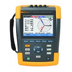
Fluke 434 3-Phase Power Quality Analyzer
No stress rentals! We help you to choose the equipment that you need, we expedite shipment, and follow up.
Features & specifications
- 3Φ Power Quality Analyzer
- Auto trend analysis in background
- System monitor gives immediate quality feedback
- Automatic transient display
- Rugged handheld instrument
- Menu-driven interface simplifies operation
- More than 7 hours operation on NiMH rechargeable battery pack
- Transfer data to PC for analysis with software (included)
- Available for rent or for sale Used
| Number of inputs (voltage) | 4 (3 phases + neutral) dc-coupled |
|---|---|
| Maximum input voltage | 1000 Vrms |
| Nominal voltage range | 50 V to 500 V according IEC 61000-4-30. Selectable from 1 V to 1000 V. |
| Maximum peak measurement voltage | 6 kV |
| Input impedance (voltage input) | 4 MΩ//5 pF |
| Bandwidth | > 10 kHz, up to 100 kHz for transient display |
| Scaling | 1:1, 10:1, 100:1, 1000:1 and variable |
| Number of inputs (current) | 4 (3 phases + neutral) dc-coupled |
| Type | Clamp on current transformer with mV output |
| Range | 1 Arms to 400 Arms with included clamps (i400s/Fluke 434) 1 Arms to 3000 Arms with optional clamps |
| Input impedance (current input) | 50 kΩ |
| Bandwidth | > 10 kHz |
| Scaling | 0.1, 1, 10, 100, 1000 mV/A, variable, i5s and i430-flex |
| Nominal frequency | 40 Hz to 70 Hz |
| Resolution (sampling) | 16 bit analog to digital converter on 8 channels |
| Maximum sampling speed | 200 kS/s on each channel simultaneously |
| RMS sampling | 5000 samples on 10/12 cycles according IEC 61000-4-30 |
| PLL synchronization | 4096 samples on 10/12 cycles according IEC 61000-4-7 |
| Waveform display | Available in Scope and Transient mode Captures 8 waveforms simultaneously Display update rate 5x per second Up to 10/12 times horizontal zoom Cursors: single vertical line showing min, max, avg reading at cursor position |
|---|---|
| Phasor | Shows real time phasor diagram Available in Scope and Unbalance mode Display update rate 5x per second |
| Meter readings | Available in Volts/Amps/Hertz, Harmonics, Power and Energy, Flicker, Unbalance and Logger mode |
| AutoTrend graph | Available in Volts/Amps/Hertz, Dips and Swells, Harmonics, Power and Energy, Flicker, Unbalance, Inrush, Mains Signaling Logger and Monitor mode Cursors: single vertical line showing with min, max, avg reading at cursor position |
| Bargraph | Available in Harmonics and Monitor mode |
| Event list | Available in Dips and Swells, Mains Signaling, Logger and Monitor mode |
| Scope | Vrms, Arms, Vcursor, Acursor, Vfund, Afund, Hz, V phase angles, A phase angles |
|---|---|
| Volts/Amps/Hertz | Vrms, Vpk, V Crest Factor, Arms, Apk, A Crest Factor, Hz |
| Dips and swells | Vrms ½, Arms ½ Captures up to 1000 events with date, time, duration, magnitude and phase identification with programmable thresholds |
| Harmonics dc, 1 to 50 | Harmonic Volts, THD Volt, Harmonic Amps, THD Amps, K Amps, Harmonic Watts, THD Watts, K Watts, Interharmonic, Interharmonic Amps (relative to fundamental or to total rms) |
| Power and energy | Watts, VA, VAR, Power factor, Cos φ/DPF, Arms, Vrms, kWh, kVAh, kVARh, peak demand interval using trend, KYZ revenue meter verification via optional input. |
| Flicker | Pst(1min), Pst, Plt, PF5, Vrms ½, Arms ½, Dc, Dmax, TD |
| Unbalance | Vneg, Vzero, Aneg, Azero, Vfund, Afund, Hz, V phase angles, A phase angles |
| Transients | Vrms, Arms, Vcursor, Acursor |
| Inrush currents | Inrush Current, Inrush duration, Arms ½, Vrms ½ |
| Mains signaling | Relative signaling voltage and absolute signaling voltage averaged over three seconds for two selectable frequencies |
| Logger | Measures and records up to 100 parameters on all 4 phases simultaneously with selecable averaging time. Captures up to 10000 events with date, time, duration, magnitude and phase identification with programmable thresholds |
| System monitor | Vrms, Arms, Harmonic Volts, THD Volts, Plt, Vrms ½, Arms ½, Vneg, Hz, dips and swells, unbalance All parameters are measured simultaneously in accordance with EN50160 Using Flagging to indicate unreliable readings according IEC61000-4-30 |
| Parameter | Range | Resolution | Accuracy |
|---|---|---|---|
| Vrms (ac+dc) | 1 Vrms to 1000 Vrms | 0.1 Vrms | ± 0.5 &337; of nominal voltage |
| Vpk | 1 Vpk to 1400 Vpk | 1 V | 5 % of nominal voltage |
| Voltage Crest Factor (CF) | 1.0 to > 2.8 | 0.01 | ± 5 % |
| Arms (ac+dc) with i400S CT |
0 kArms to 20.00 kArms 0 Arms to 40/400 Arms |
0.001 Arms to 10 Arms 0.1 to 1 Arms |
± 1 % ± 5 counts ± 1 &337; ± 5 counts |
| Apk using 1 mV/A scaling | 0 Apk to 5500 Apk | 1 A | ± 5 % |
| A Crest Factor (CF) | 1 to 10 | 0.01 | ± 5 % |
| 50 Hz nominal frequency 60 Hz nominal frequency |
42.50 Hz to 57.50 Hz 51.00 Hz to 69.00 Hz |
0.01 Hz 0.01 Hz |
± 0.01 Hz ± 0.01 Hz |
| Parameter | Range | Resolution | Accuracy |
|---|---|---|---|
| Vrms½ (ac+dc) | 0.0 % to 200 % of nominal voltage | 0.1 Vrms | ± 1 % of nominal voltage |
| Arms½ (ac+dc) with i400s | 0 Arms to 20,000 Arms 0 Arms to 400 Arms |
0.001 Arms to 10 Arms 0.1 Arms and 1 Arms |
± 2 % ± 10 counts |
| Threshold levels | Programmable thresholds in percent of nominal voltage Event detection based upon ½ cycle rms voltages Captures dips, swells, interruptions and rapid voltage changes |
||
| Duration | hhh,mm,ss,mmm | Half cycle | One cycle |
| Parameter | Range | Resolution | Accuracy |
|---|---|---|---|
| Harmonic order (n) | DC, 1 to 50 grouping: harmonic groups according to IEC 61000-4-7 | ||
| Inter-Harmonic order | Off, 1 to 49 grouping: harmonic and interharmonic subgroups according to IEC 61000-4-7 | ||
| Vrms Relative (%f) Vrms Absolute |
0.0 % to 100.0 % 0 Vrms to 1000 Vrms |
0.1 % 0.1 Vrms |
± 0.1 % ± n x 0.1 % (± 0.4 % for %r) ± 5 % ± 2 counts |
| Arms Relative (%f) Arms Absolute |
0.0 % to 100.0 % 0.0 mV to 4000 mV x clamp scaling |
0.1 % 1 mVrms x clamp scaling |
± 0.1 % ± n x 0.1 % (± 0.4 % for %r) ± 5 % ± 5 counts |
| Watts - Relative: (Harmonics only - Absolute: |
0.0 % to 100.0 % depends on clamp and voltage scaling |
0.1 % | ± n x 2 % ± 5 % ± n x 2 % ± 10 counts |
| DC - Relative: DC - Absolute V: DC - Absolute A: DC - Absolute W: |
0.0 % to 100.0 % 0.0 V to 1000 V 0.0 mV to 4000 mV x clamp scaling depends on clamp and voltage scaling | 0.1 % 0.1 V 1 mVrms x clamp scaling 0.1 V depends on scaling |
± 0.1 % V and A (± 2 % Watt) ± 5 % ± 10 counts ± 5 % ± 10 counts ± 5 % ± 10 counts |
| THD(n=40) - (relative %f or %r) | 0.0 % to 100.0 % | 0.1 % | ± 2.5 % V and A (± 5 % Watt) |
| Hz | 0 Hz to 3500 Hz | 1 Hz | ± 1 Hz |
| Phase angle | -360 ° to +0 ° | 1 ° | ± n x 1.5 ° |
| Case design | Rugged, shock proof with integrated protective holster |
|---|---|
| Drip and dust proof | IP51 according to IEC60529 when used in tilt stand position |
| Shock and vibration | Shock 30 g, vibration: 3 g sinusoid, random 0.03 g2/Hz according to MIL-PRF-28800F Class 2 |
| Display type | Bright full-color LCD with CCFL backlight, 80 cd/m2 |
| Display size | 115.2 mm x 86.4 mm (4.5 in x 3.4 in) |
| Resolution | 320 x 240 pixels |
| Contrast and brightness | User-adjustable, temperature compensated |
| Screen memory | 50 screen memories |
| Data memory | 10 data memories for storing data including recordings |
| Logger | User configurable shared memory, up to 7 MB |
| Limit templates | 2 preprogrammed, 2 administrator (programmable via FlukeView®), 2 user locations |
| Real-time clock | Time and date stamp for AutoTrend, Transient display and SystemMonitor |
| Dimensions & weight | (256 x 169 x 64)mm, (10 x 6.5 x 2.5)in, 2 kg (4.5 lb) |
| Line power | Switchable 115 V, 230 V adapter with country specific plug |
| Power adapter | 15 V dc to 23 V dc; use only power adapter BC430 |
| Battery power | Rechargeable NiMH BP190 (installed) |
| Battery operating time | > 7 hours |
| Battery charging time | 4 hours, 8 hours for/006 version (instrument off) |
| Power saving | Adjustable time for dimmed backlight with on screen power indicator |
| Measurement standards | IEC 61000-4-30 Class-A |
| Measurement performance | IEC 61000-4-30 Class-B |
| Power quality standard | EN 50160 |
| Flicker standard | IEC 61000-4-15 |
| Harmonics standard | IEC 61000-4-7 |
| Cross talk between V inputs | -60 dB at nominal frequency |
| Cross talk V to I input | -95 dB at nominal frequency |
| Safety standards | IEC/EN 61010-1-2001; CAN/CSA C22.2 No 61010-1-04; UL std No 61010-1 Safety Requirements for Electrical Equipment for Measurement, Control and Laboratory Use, Part 1: General requirements. Rated: 600 V CAT IV/1000 V CAT III Pollution Degree 2 |
| Max voltage on banana input | 1000 V CAT III/600 V CAT IV |
| Max voltage on current BNC input | 42 Vpeak |
| Operating temperature | 0 °C to +50 °C (32 °F to 122 °F) battery only, 0 °C to +40 °C (32 °F to 104 °F) with adapter, within spec +15 °C to +35 °C (59 °F to 95 °F) |
| Storage temperature | -20 °C to +60 °C (-4 °F to +140 °F) |
| Printers and Interface | Serial, optically isolated. Compatible with PM9080 (RS-232) or OC4USB (USB) Baud rate: 1200, 2400, 9600 to 115 kB |
| Print protocol | Epson FX/LQ, Deskjet, LaserJet , DPU-414 |